

Scarlet Build Guide
Welcome to the build guide for the Scarlet Number Pad PCB
For firmware flashing and general Scarlet info including DIY kit availability please see the main Scarlet page. The main page also has a list of components and where to source them if you are producing your own board from the open source files.
Required Equipment
To build Scarlet you will need the following equipment that is not included in the DIY kit.
- A soldering iron and solder, I recommend leaded solder if available and reasonably small bevel tip on the iron.
- Side cutters for trimming the legs of the soldered components.
- No clean solder paste, this is required for drag soldering the USB-C port.
- Solder wick, not required but very useful if you bridge any solder points.
- Three 2u stabilizers for the 0, Enter and + keys.
- 17 x 5 Pin PCB mount cherry style switches
- A USB-C cable
- A case / standoffs. Currently there is no case for Scarlet but one is being worked on, there are however six M2 holes in the PCB for mounting.
Scarlet Build Guide – Included Components
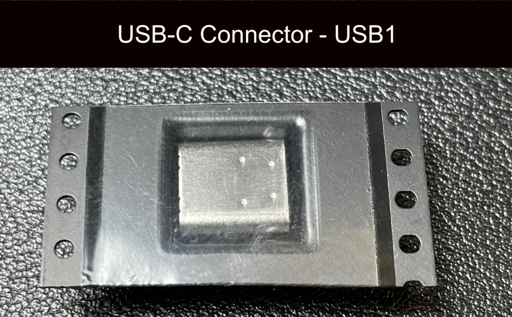
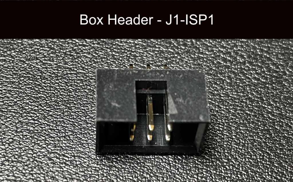
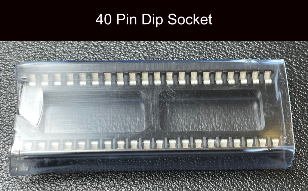
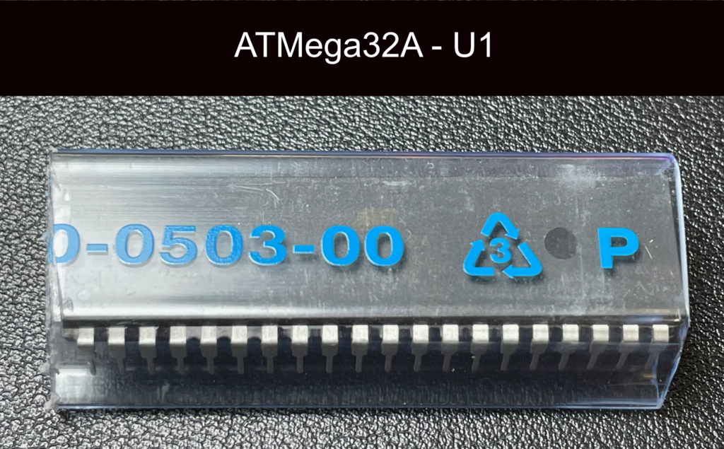
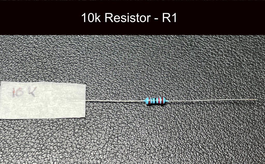
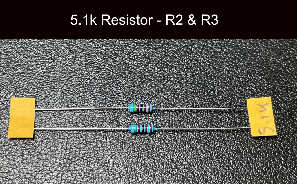
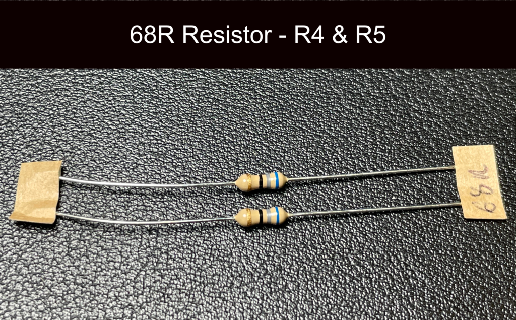
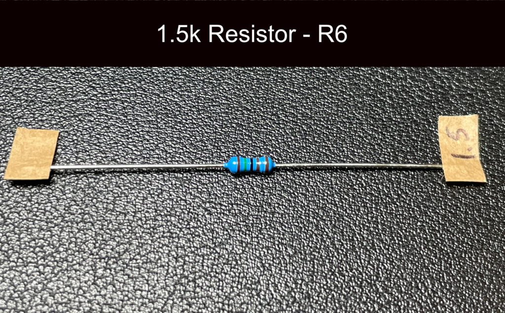
Alongside the PCB, the following components are included and are pictured here for easy identification (Components in DIY kits may look slightly different to pictures but will be compatible).
Scarlet Build Guide – Building
If you are using the components from the DIY kit or sourcing them yourself here is the Scarlet Build Guide.
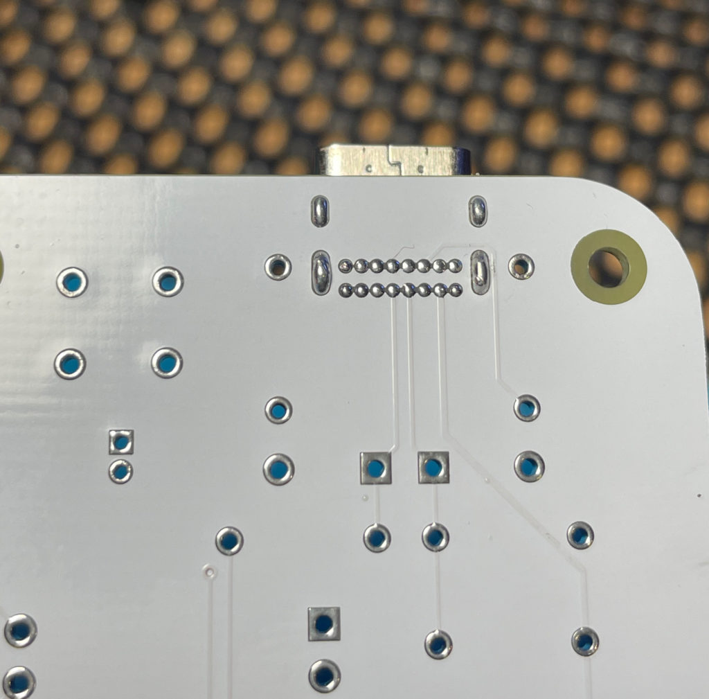
Step 1 – The USB-C Connector
The first stage is to attach the USB-C connector, this will be the most difficult part of the build as it uses a technique that is somewhat different to standard through hole soldering. We are going to use a technique called drag soldering (there various videos on the internet detailing this, here is a representative one that will give you more information on this soldering method).
Firstly insert the USB-C connector and using the standard soldering technique solder the four large ground points that will hold the connector in place.
Once the connector is in place, flush and the solder has cooled, take the no clean solder paste and apply it across the 16 pin small connectors ensuring they are covered.
Apply a small amount of solder to your hot iron and drag it across the pins, the flux should stop solder bridges and the small pins should be connected cleanly.
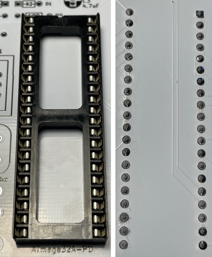
Step 2 – Microprocessor Socket
The next stage is to solder in the socket for the microprocessor, ensure you keep the socket flush and that you alight the top of the socket (with the small cutout) at the top of the board closest to the USB-C connector.
I prop one side of the board to the same height as the socket when soldering to ensure it stays flush. One tip is to solder the four corners first keeping downward pressure to make sure the socket is flat against the board.
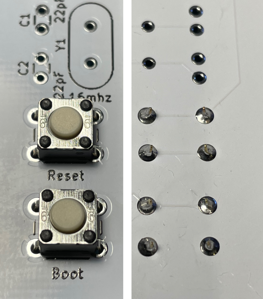
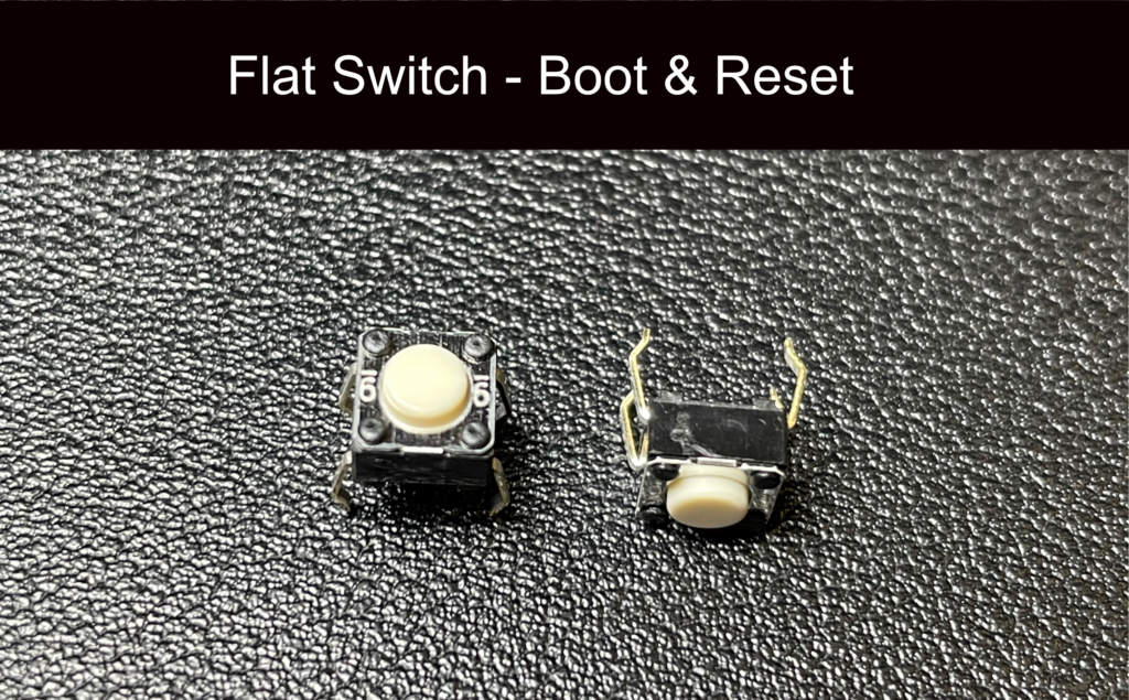
Step 3 – Boot & Reset Buttons
The buttons are next to be soldered in, you do not have to worry about the orientation of them, they can only fit one way up and will clip into place making them easy to solder.
The Boot and Reset buttons are used when programming new QMK firmware or flashing the bootloader.
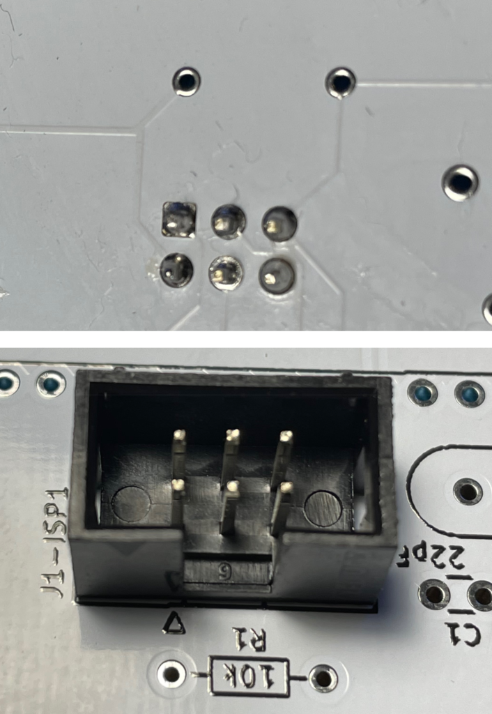
Step 4 – The ISP Header Connector
Make sure you align the connector the same way as the picture on the board indicates, the cut out notch should face the R1 resistor as shown. When soldering in the connector it is recommended you prop the other side of the PCB up with something of a similar height, (maybe some paper or a small book).
When soldering apply an amount of downward pressure to keep the connector flush to the board, if needs be you may have to heat the solder joins afterwards and whilst pressing the connector flush (if you do this make sure you do not touch the pins as they will be hot!).
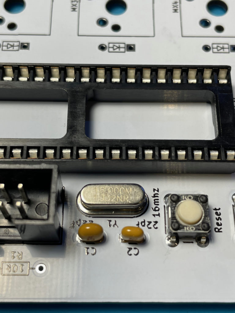
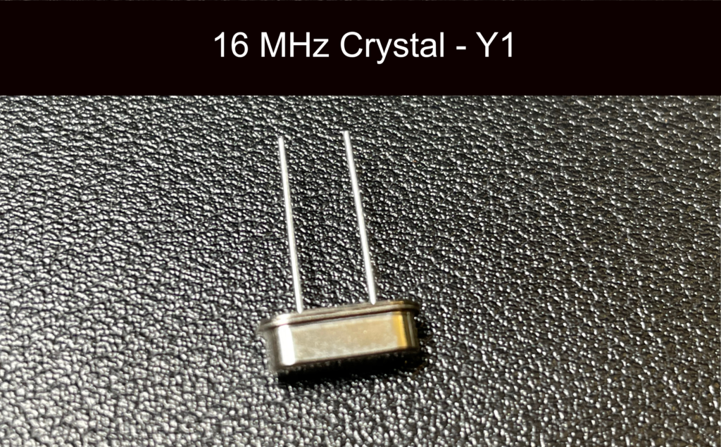
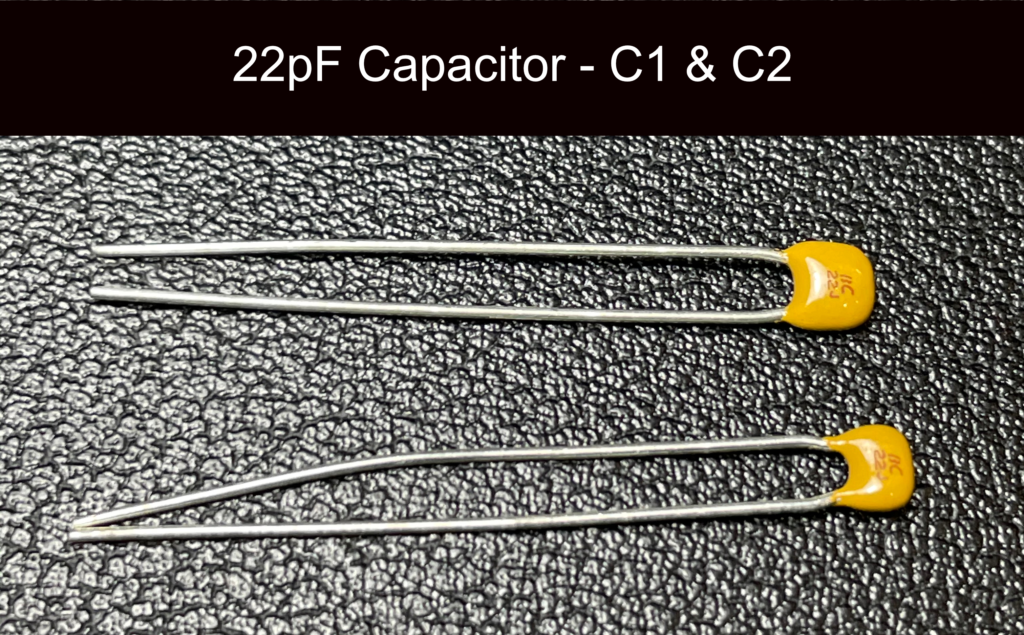
Step 5 – The Crystal And Associated Capacitors
These should both be straightforward to solder and none of these components have a particular orientation.
The crystal is soldered to Y1 and the two 22pF capacitors go into C1 and C2 respectively.
Clip the legs when you are done.
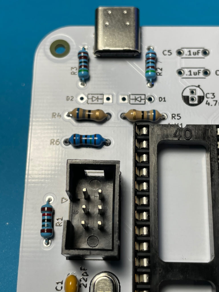
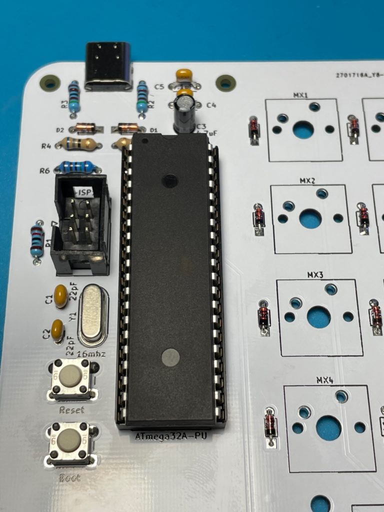
Step 6 – Resistors
Match up the resistors to their places on the board using the parts list above and the markings on the board. Each can be simply soldered onto the board and none of them are directional so they can be soldered in either way around.
Try to keep the legs short so the sit flush to the board, you can see an example of the resistor placement in the picture. Ensure R1 through R6 are in place before proceeding.
Clip the legs when you are done.
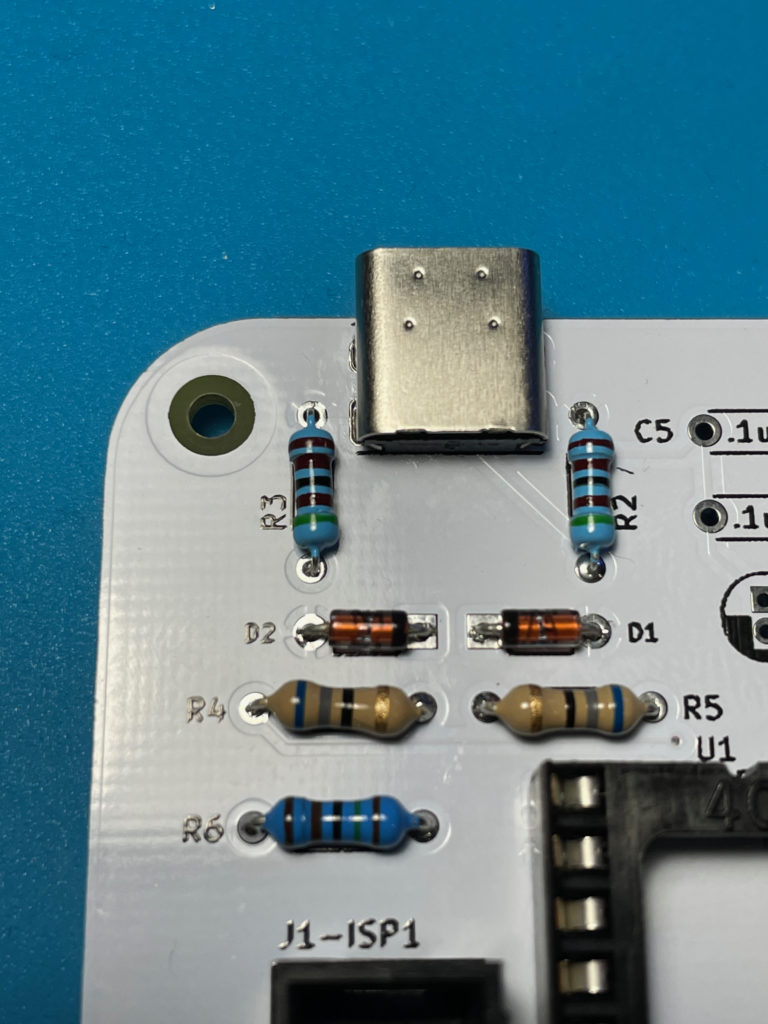
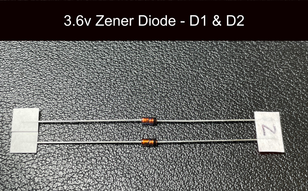
Step 7 – Zener Diodes
CAUTION – Do Not Mix These Diodes Up With The 1N4148 Diodes – They Are Not The Same!
Locate D1 and D2 on the board, you will see on the PCB markings they have a little arrow that points towards a bar. This indicates the direction that the diode must be inserted. If you look at the Zener diodes you will see that they have a little black bar on one end, this must face towards the bar on the PCB marking.
With this correctly aligned you can solder the same way you have done with the resistors.
Clip the legs when you are done.
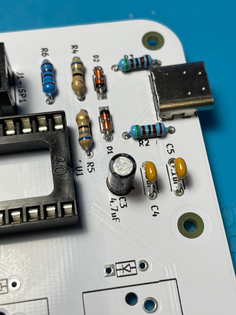
Step 8 – Bypass Capacitors
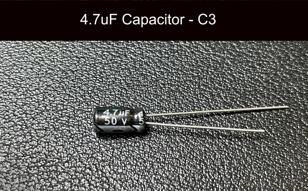
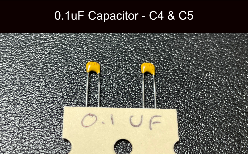
There are three capacitors in this part of the board, C3, C4 and C5.
C4 and C5 are non directional and can be soldered in either direction. C3 however is an electrolytic capacitor and must be fitted in a specific orientation.
If you look at the C3 capacitor you will see that it had one leg shorter than the other, this leg is the negative connection.
On the PCB where C3 is marked you will see that one half of the capacitor marking is white and the other is black. You need to align the negative side of the capacitor (shorter leg) to the black section of the PCB marking (furthest away from the USB-C connector).
Clip the legs when you are done.
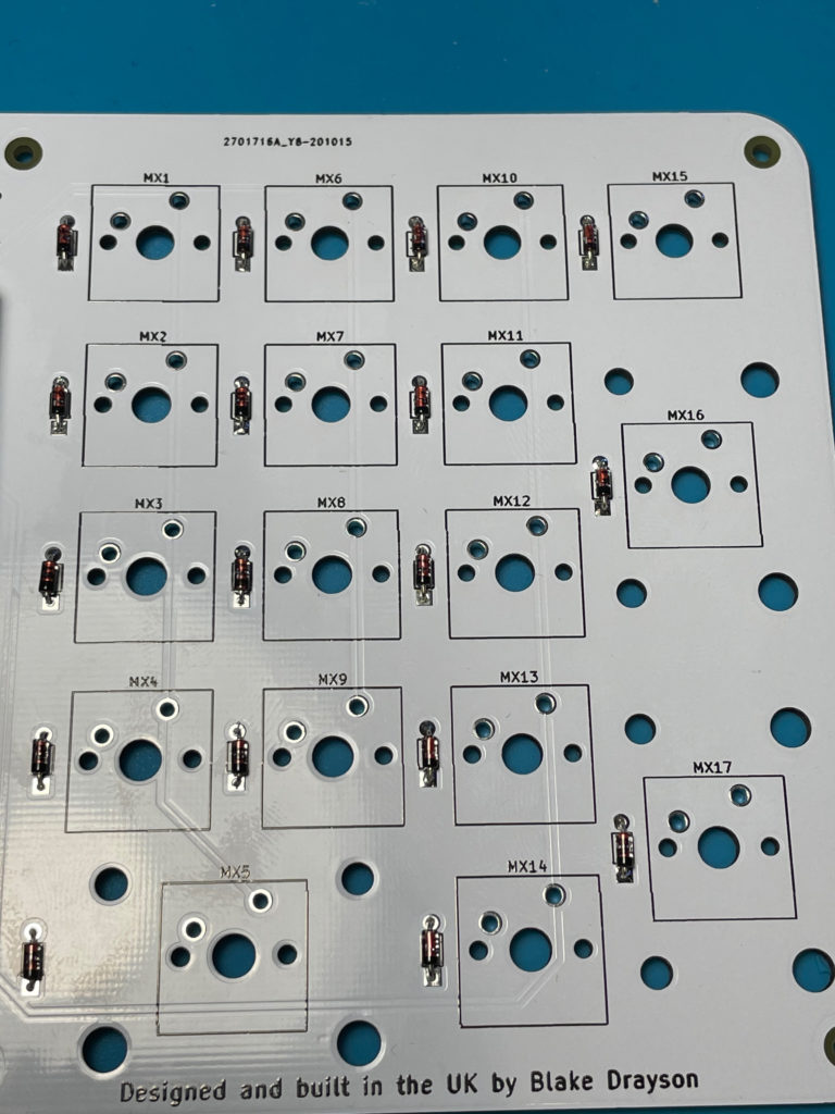
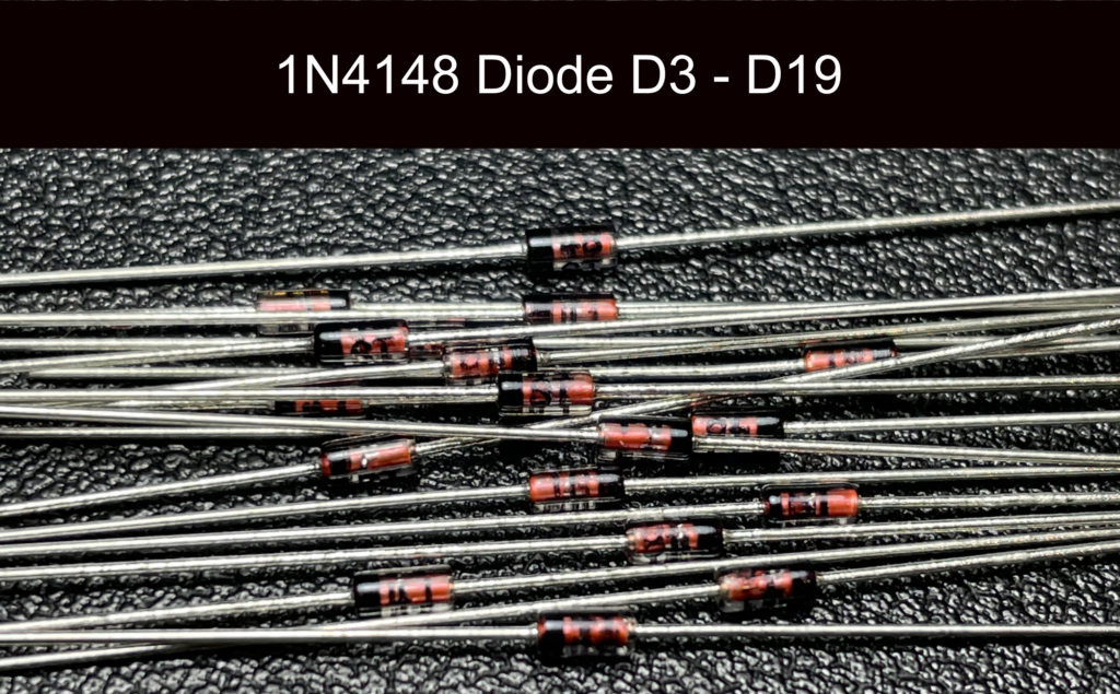
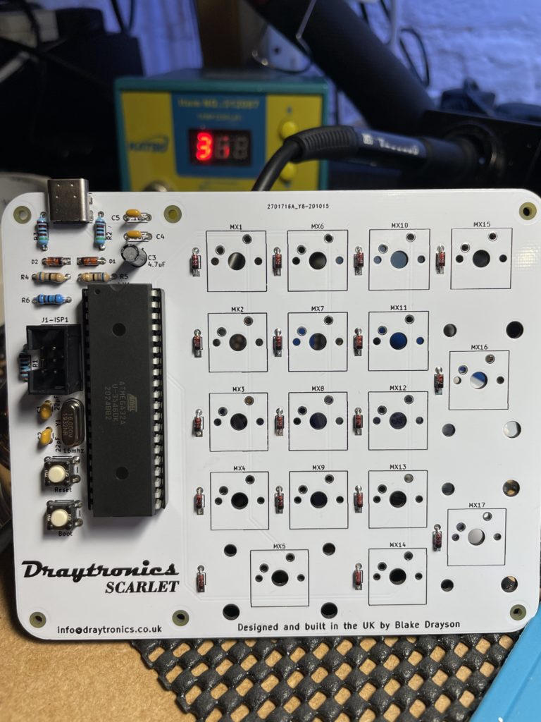
Step 9 – Switch Diodes
CAUTION – Do Not Mix These Diodes Up With The Zener Diodes – They Are Not The Same!
There are now seventeen diodes to solder they sit next to each switch and require the same orientation as the zener diodes from before. Align the black bar on the diode to the bar on the PCB marking.
Clip the legs when you are done.
Step 10 – Socket The Microcontroller
The microcontroller now needs to be inserted into the socket, on the chip there is a little circular mark at the top of one edge that indicates the orientation. Make sure you have this facing towards the top of the board when you insert the chip.
Take your time and don’t use excessive force to insert the chip, make sure you align the pins before pushing down.
You will need to likely bend the pins inward slightly to allow them to align, this is perfectly normal.
Step 11 – Test Before Fitting Switches
Before you fit any switches now is a good time to test that the keyboard works, plug the keyboard into your computer and using a wire or tweezers short each switch connection to make sure they send a keypress.
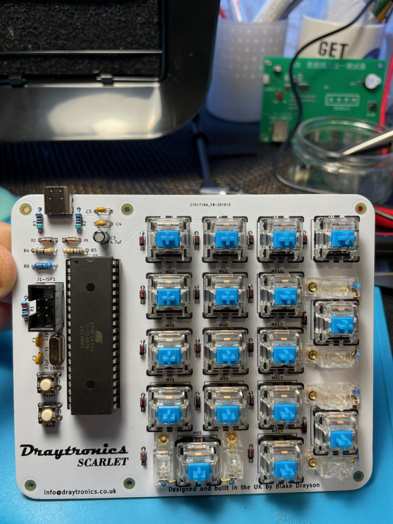
Step 12 – Solder Your Switches & Fit Stabilisers
Fit the three required 2U stabilisers, you can use clip mount or screw mount types, I personally prefer screw but clip will work.
You can now insert and solder your switches, make sure the switches are pushed fully into the PCB and clip into the mount holes. Check they are flush before you solder them
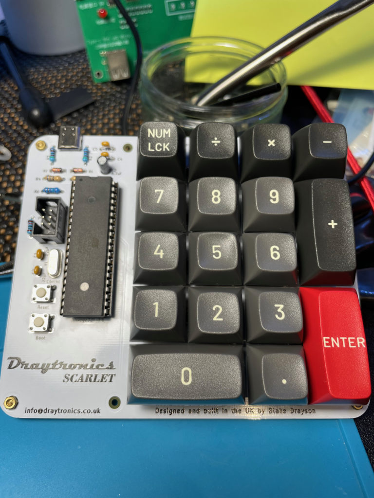
Step 13 – Add Keycaps
Finally you can add your keycaps and plug your board in, if you have pre-flashed chip (all DIY kits come with flashed chips) the keyboard should now work. If you have a blank chip you can follow the programming guide on the main Scarlet page.
To keep up to date join our mailing list.
By clicking submit, you agree to share your e-mail address with the site owner and MailChimp to receive marketing, updates, and other e-mails from the site owner. Use the unsubscribe link in those e-mails to opt out at any time.