

Scarlet Firmware Programming Guide
Welcome to the Scarlet firmware programming guide
For a build guide and general Scarlet information including DIY kit availability please see the main Scarlet page. The main page also has a list of components and where to source them if you are producing your own board from the open source files.
Scarlet Firmware Programming – Assumptions
This guide will assume you are using a ProMicro as a programmer for the bootloader. It is possible to use different devices such as a Raspberry Pi but it will be left to the reader to adapt the guide to suit their needs.
Scarlet Firmware Programming – Bootloader & Fuses
Preparing the programmer
First must flash a specific firmware to the Pro Micro, the firmware in question is derived from the QMK ISP Flashing Guide. Download the firmware and QMK toolbox, install QMK toolbox and connect your Pro Micro.
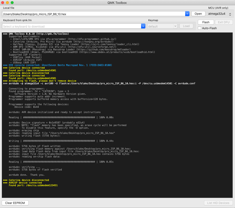
You should open QMK toolbox and see that it has detected the Pro Micro, it should say something similar to the following.
*** Caterina device connected
    Found port: /dev/cu.usbmodem14501
At the top of the page, click open and locate the firmware file you downloaded. Then make sure that the MCU is set to ‘atmega32u4’ (this is only if you are using a Pro Micro, otherwise the MCU will be different).
When ready click flash and you should see an output similar to the following (click for large version), you will also see that the board has been disconnected and reconnected and now reads as an AVRISP device, this confirms it is correctly configured and ready to program other microcontrollers.
Connecting ISP pins
Connect the Pro Micro to J1-ISP1 using the following diagram and wiring matrix.
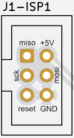
***Scarlet / Pro Micro Wiring Matrix***

Pro Micro 10 (B6)  <-> J1-ISP1 reset
Pro Micro 15 (B1)  <-> J1-ISP1 sck
Pro Micro 16 (B2)  <-> J1-ISP1 mosi
Pro Micro 14 (B3)  <-> J1-ISP1 miso
Pro Micro VCC      <-> J1-ISP1 +5V
Pro Micro GND      <-> J1-ISP1 GND
Compiling and flashing
With the programmer connected we can proceed to flashing the bootloader.
You will require a working build environment and need to download the pre-configured fork of USBaspLoader. Once this is done open a terminal in the root of USBaspLoader.
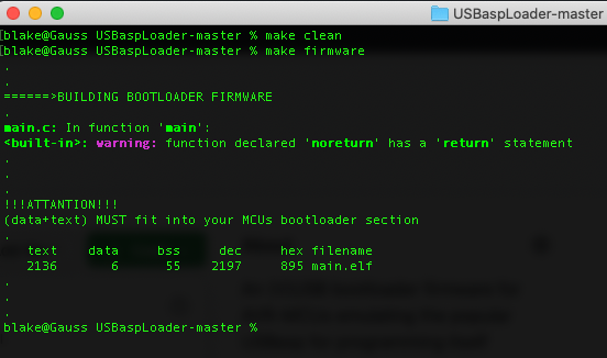
Execute the following and make sure the bootloader compiles before proceeding.
make clean
make firmware
The output should be similar to the following.
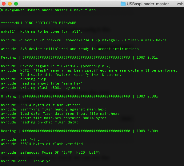
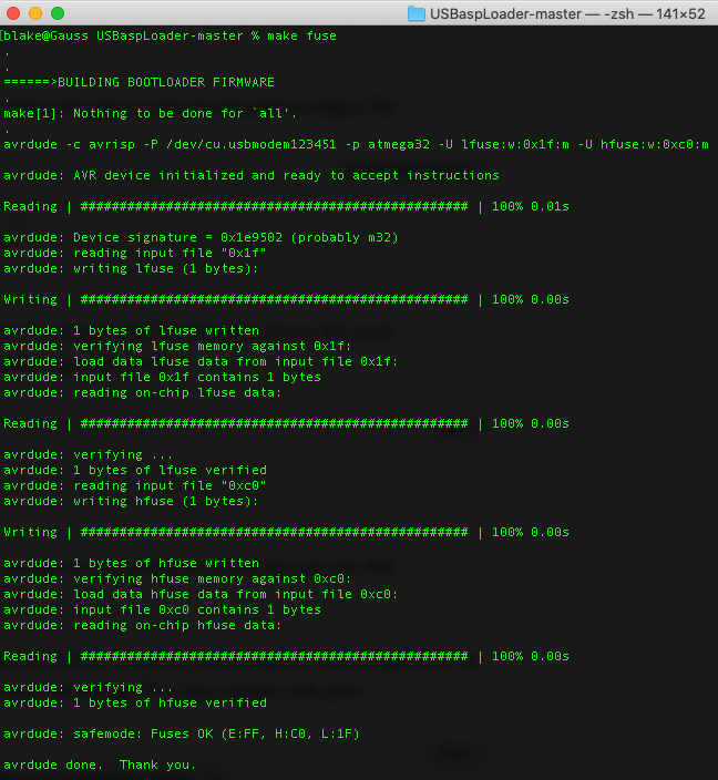
When ready execute the following commands to flash the bootloader and set the fuses.
make flash
make fuse
The output should be similar to the following.
Scarlet Firmware Programming – QMK Firmware
You will require a working QMK build environment, please ensure this is setup before starting.
Scarlet has been added to the QMK and is available in the latest revision, please make sure you sources are up to date.
Compiling and flashing
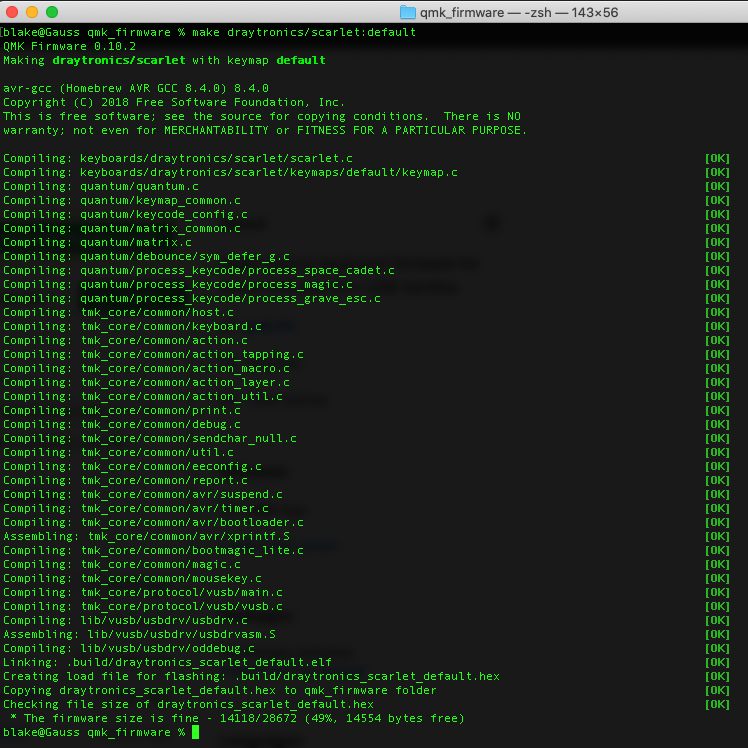
From the root QMK folder execute the following command to build the firmware.
make draytronics/scarlet:defaultThe output should be similar to the following.
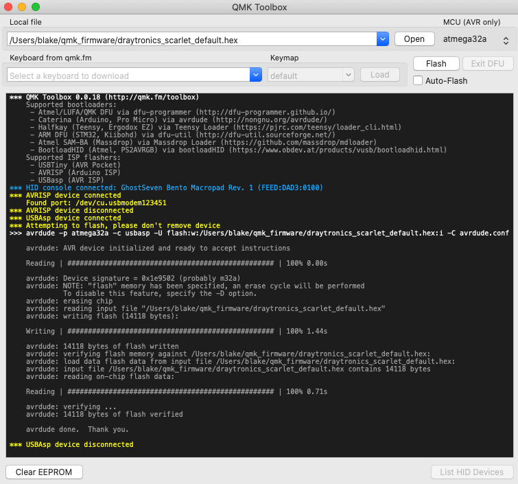
To flash the firmware complete the following process.
- Open QMK Toolbox
- Open the draytronics_scarlet_default.hex
- Set the controller to atmega32a
- Ensure the programmer is disconnected from the J1-ISP1 header
- Hold down the boot button
- Connect the keyboard to your computer via the USB-C port
- Keep the boot button held down
- Press flash in QMK Toolbox
Scarlet is now programmed and ready to use, you should see output similar to the following.
To keep up to date join our mailing list.
By clicking submit, you agree to share your e-mail address with the site owner and MailChimp to receive marketing, updates, and other e-mails from the site owner. Use the unsubscribe link in those e-mails to opt out at any time.